

High Speed Pressure Vacuum Valve with Heat Devices
P/V Valve with heat devices is for the ships which sailing on the cold or Ice area the vapor or crystallization of goods may be produced.
- Material: Carbon Stee, SUS 304/304L/316L
- Sizes: DN50-DN250
- Connection: Universal Flange
- Certificate: CCS/ABS/EC
- Features: Aseismatic and anti–collision, Heat Devices
- Standars: .IMO.MSC/Circ.677, IS015364, IMO.MSC/Circ1324, etc
Introduction
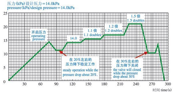
The DF-ISO High Speed Pressure Vacuum Relief Valve will open completely only when the system pressure reached the setting opening pressure because of the special designing of the pressure valve. Under the normal load rate, after the valve open, the pressure of line and the cabin system will fall by 20% to 50%, then work steadily and maintain the flow rate of 30m/s. In work, the system pressure won’t increase or decrease suddenly.
The high-speed export valve won’ t be impacted and shocked under the allowed rate of loading. This series of valves also can install a magnetic control mechanism, which can deal with the problem of valve vibration on the voyage and can minimum the steam loss.
The basic leakage of DF -ISO series pressure vacuum valve is zero when the wording pressure is set at 80%, and can be chosen to load the goods which require zero leakage. This series of pressure vacuum valve is one of the most advanced products in the world. The series of valves can work under -20 ℃ to +60 ℃ regularly, when the valves freeze, they can work regularly after ice breaking.
Technical Data
1. The High Speed Pressure Vacuum Relief Valve with different specifications have the same diameter and performance parameter;
2. The opening pressure of the vacuum valves are -3.5kPa, the opening pressure of the pressure valves for the oil tank is 14kPa, but for the chemical tank is 20kPa. The opening pressure of the pressure may be different, but the differences of opening pressure and flow range is inapparent if the pressure valves have the same diameter.

Pressure Graph
The standardized flange of the high-velocity relief valve is connected with the pipe flange of the cargo oil tank, and the mixed compressed gas will be formed when the cargo oil tank is loading cargoes. The valve on the pressure valve with the block will spring out in a flash, at the same time the valve will open while the pressure of the compressed gas reaches to the set pressure (the oil tank is 14KPa, chemical tank is 20KPa), then releasing the mixed compressed gas to the air with the speed of more than 30m/s (it will be more then 30m/s under the regular operation).
The vacuum will be formed while the cargo oil is tank unloading. the valve will open automatically while the vacuum reaches to the set pressure (it is -3.5KPa), and then the air will go into the tank through the flame screen.
If the pressure is too high while the ship is sailing, the high-velocity relief valve will automatically release the pressure and balance it.
The Pressure-Graph of Pressure Valve
The Pressure-Graph of Vacuum Valve

The simulant loading and unloading tests shall be done on each graph of the pressure valve according to the operation pressure which provide by Ship Desgning & Research Institute, then provide the following graph and flow datum under different pressure to the ship-owner.
Pressure operation testing shall be done on each CF-ISO high-velocity relief valve, make sure it can be operated smoothly during the process of increasing or decreasing the pressure.
As the above-mentioned, assemble the pressure/vacuum valve with different specifications on the ship according to its loading rate, ensure the pressure of the tank is under the specific working pressure, then the pressure valve and vacuum valve will work smoothly no matter the pressure increases or decreases.
Structure

Each Part Name & Material
| Serial No. | Parts | Quantity | Material | Remarks |
| 1 | P-valve base | 1 | Stainless Steel | Stainless Steel |
| 2 | Water nozzle | 1 | Stainless Steel | Stainless Steel |
| 3 | P-valve seat | 1 | Stainless Steel | Stainless Steel |
| 4 | P-valve disc | 1 | Stainless Steel | Stainless Steel |
| 5 | Matching block | 1 | Stainless Steel | Stainless Steel |
| 6 | P-valve body (A) (B) | 1 | Stainless Steel | Stainless Steel |
| 7 | Conducting machine | 1 | Stainless Steel | Stainless Steel |
| 8 | Handle | 1 | Stainless Steel | Stainless Steel |
| 9 | V-valve body | 1 | Stainless Steel | Stainless Steel |
| 10 | Matching block | 1 | Stainless Steel | Stainless Steel |
| 11 | V-valve disc | 1 | Stainless Steel | Stainless Steel |
| 12 | V-valve seat | 1 | Stainless Steel | Stainless Steel |
| 13 | Flame screen | 2 | Stainless Steel | Stainless Steel |
| 14 | Flame screen gland | 1 | Stainless Steel | Stainless Steel |
| 15 | Nameplate | 1 | Stainless Steel | Stainless Steel |
| 16 | Climbing pole | 1 | Stainless Steel | Stainless Steel |
| 17 | Gas-freeing cover or V-valve cover | 1 | Stainless Steel | Stainless Steel |


